
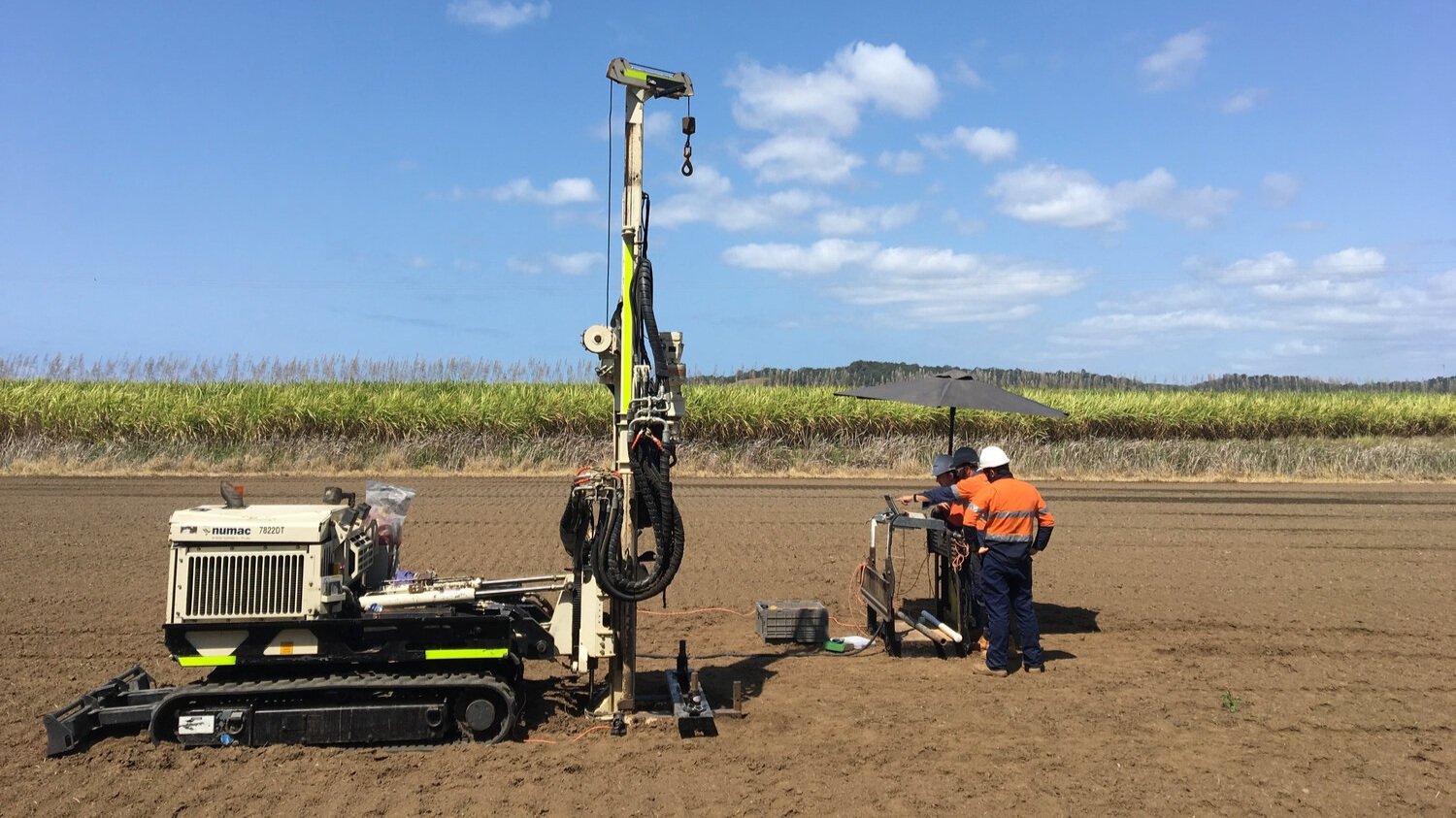
Groundwater Monitoring Well Installation
INSTALLATION OF PVC MONITORING WELLS FOR GROUNDWATER SAMPLING

All monitoring well installation materials meet Australian standards and the highest industry expectations.
Usage of Monitoring Wells
Groundwater Quality Monitoring: Detect pollutants, assess contamination spread, and ensure compliance with environmental regulations.
Hydrogeological Studies: Analyze aquifer properties, water table fluctuations, and recharge rates.
Remediation Efforts: Track the effectiveness of groundwater cleanup initiatives.
Compliance Monitoring: Meet legal and regulatory requirements for industries, landfills, and other sites.
Construction of Monitoring Wells
Site Selection:
Strategic placement based on hydrogeology and project goals.
Proximity to contamination sources, aquifers, or recharge zones.
Design:
Diameter: Typically ranges from 2 to 6 inches.
Casing Material: Selected for chemical compatibility (e.g., PVC, stainless steel).
Screened Interval: Positioned in the target zone to allow water flow without sediment infiltration.
Drilling Methods:
Auger Drilling: For shallow monitoring wells in unconsolidated materials.
Mud or Air Rotary Drilling: Suitable for deeper monitroing wells.
Sonic drilling - Suitable for installation of groundwater wells in challenging formations such as sands, silts, gravels and mine waste or tailings.
Direct Push Technology: Ideal for temporary and pre-packed monitoring wells or rapid installation.
Monitoring Well Installation:
Install of casing and screen, should be threaded joints to avoid use of adhesives that may contain contaminants.
Adding clean sand or gravel around the screen for filtration and stablisisaiton.
Sealing with bentonite above the screen to create a low permeability seal.
Grout the annular space back to prevent surface water contamination.
Install appropirate headworks to protect the well from damage or contamination.
Development and Testing:
Flushing and purging to remove fine materials using high pressure air or mechanical tools (Bailers).
Testing flow rates and water quality to ensure monitoring accuracy.
Maintenance:
Regular cleaning to prevent clogging.
Inspections for structural integrity and data reliability.
Maintenance of well heads.
Products Used in Monitoring Well Construction
Casing and Screens:
Materials:
PVC (Polyvinyl Chloride): Lightweight, corrosion-resistant, cost-effective.
Stainless Steel: High durability, chemical resistance, suitable for harsh environments.
Purpose: Provides structural integrity and facilitates groundwater flow.
Gravel Pack or Sand Pack:
Surrounds the monitoring well screen to prevent sediment infiltration while allowing water flow.
Sealing Materials:
Bentonite: Expanding clay used to seal gaps and prevent surface contamination.
Grout: Cement-based material for additional sealing and stabilization.
End Caps and Centralizers:
Prevent debris entry from the base of the installation and keep the well centered in the borehole.
Sampling Equipment:
Bailers, pumps, or passive samplers designed for precise groundwater extraction.
Potential Issues with Well Design and Installation
Improper Site Selection:
Poor placement can lead to inaccurate data or failure to intercept contamination plumes.
Faulty Design:
Incorrect screen size or interval placement can hinder water flow or allow sediment infiltration.
Material Compatibility:
Incompatible casing materials may degrade, causing contamination or structural failure.
Inadequate Sealing:
Poorly sealed wells can allow surface water intrusion or cross-contamination between aquifers.
Construction Errors:
Drilling damage to surrounding formations can alter natural groundwater flow.
Well Development:
Insufficient flushing and purging may leave debris, leading to data inaccuracy.
Maintenance Neglect:
Lack of cleaning or inspection can result in clogging, equipment damage, or reduced performance.
MONITORING DESIGN AND INSTALLATION TECHNIQUES
Monitoring wells are indispensable tools for understanding and managing groundwater systems. Their success depends on careful planning, high-quality materials, skilled construction, and ongoing maintenance to mitigate risks and ensure reliable performance.CONSTRUCTION OF MONITORING WELLS
Monitoring well construction techniques
The borehole should be bored, drilled, or augered as close to vertical as possible, and checked with a plumb bob or level. Deviation from plumb should be within 1° per 20 m of depth. Slanted boreholes are undesirable and should be noted in the boring logs and final construction logs. The depth and volume of the borehole, including the over-drilling if applicable, should have been calculated and the appropriate materials procured prior to drilling activities.
Screen and casing
The well casings should be secured to the well screen by flush-jointed threads and placed into the borehole and may be plumbed by the use of centralisers. Another method of placing the well screen and casings into the borehole and plumbing them at the same time is to suspend the string of well screen and casings in the borehole by means of a hoist on the drill rig. This wireline method is especially useful if the borehole is deep and a long string of well screen and casings have to be set and plumbed. No lubricating oils or grease should be used on casing threads. No glue of any type should be used to secure casing joints. Teflon "O" rings can also be used to insure a tight fit and minimize leakage; however, "O" rings made of other materials are not acceptable if the well is going to be sampled for organic compound analyses.
Centralisers
Centralisers can be used to plumb a well, but centralizers should be placed so that the placement of the filter pack, bentonite pellet seal, and annular grout will not be hindered. Centralisers placed in the wrong locations can cause bridging during material placement. Monitoring wells less than 20m deep generally do not need centralisers. If centralisers are used they should be placed below the well screen and above the bentonite pellet seal. The specific placement intervals should be decided based on site conditions.
Hollow auger installation
When installing the well screen and casings through hollow-stem augers, the augers should be slowly extracted as the filter pack, bentonite pellet seal, and grout are tremied and/or poured into place. The gradual extraction of the augers will allow the materials being placed in the augers to flow out of the bottom of the augers into the borehole. If the augers are not gradually extracted, the materials (sand, pellets, etc.) will accumulate at the bottom of the augers causing potential bridging problems.
Placing the filter pack
After the string of well screen and casing is plumb, the filter pack material should then be placed around the monitoring well screen to the designated installation depth. With cased drilling methods, the sand should be poured into the casing or augers until the lower portion is filled. The casing or augers are then withdrawn, allowing the sand to flow into the evacuated space. With hollow stem augers, sand should always fill the augers 6-12 inches, maintained by pouring the sand while checking the level with a weighted tag line. The filter pack sand in open boreholes should be installed by tremie methods, using water to wash the sand through the pipe to the point of placement.
Bentonite seal
After the filter pack has been installed, the bentonite seal should be placed directly on top of the filter pack to an unhydrated thickness of 1 metre. After the pellet seal has hydrated for the specified time, the grout should then be pumped by the tremie method into the annular space around the casings. The grout should be allowed to set for a minimum of 24 hours before the surface pad and protective casing are installed.
Surface pad
After the surface pad and protective casing are installed, bumper guards should be installed (if needed). The bumper guards should be placed around the concrete surface pad in a configuration that provides maximum protection to the well. Each piece of steel pipe or approved material should be installed into an 8- to 10-inch diameter hole, to a minimum depth of 2 feet below ground surface, and filled with concrete. As previously stated, the bumper guard should extend above the ground surface a minimum of 3 feet. The total length of each bumper guard should be a minimum of 5 feet.
Monument covers
After the wells have been installed, the outer protective casing should be painted with a highly visible paint. The wells should be permanently marked with the well number, date installed, site name, elevation, etc., either on the cover or an appropriate place that will not be easily damaged and/or vandalised.
Flush mount well covers
If the monitoring wells are installed in a high traffic area such as a parking lot, in a residential yard, or along the side of a road it may be desirable to finish the wells to the ground surface and install water-tight flush mounted traffic and/or man-hole covers. Flush mounted traffic and man-hole covers are designed to extend from the ground surface down into the concrete plug around the well casing. Although flush mounted covers for monitoring wells may vary in design, they should have seals that make the unit water-tight when closed and secured. The flush mounted covers should be installed slightly above grade to minimize standing water and promote runoff. Permanent identification markings should be placed on the covers or in the concrete plug around the cover. Expansive sealing plugs should be used to cap the well riser to prevent infiltration of any water that might enter the flush cover.
Surface casing
Surface casing should be constructed when there is reason to believe that interconnection of two aquifers by well construction may cause cross-contamination or when flowing sands make it impossible to install a monitoring well using conventional methods. A highly contaminated surface soil zone may also be cased off so that drilling may continue below the casing with reduced danger of cross contamination. A pilot borehole should be bored through the overburden and/or the contaminated zone into the clay confining layer or bedrock. An outer casing should then be placed into the borehole and sealed with grout. The borehole and outer casing should extend into tight clay or a minimum of .5 m and into competent bedrock a minimum of .25 m. The total depths into the clay or bedrock will vary, depending on the plasticity of the clay and the extent of weathering and/or fracturing of the bedrock. The size of the outer casing should be of sufficient diameter to allow for subsequent drilling methods.
The outer casing should be grouted by the tremie, pressure grouted or via displacement,The grout should be pumped into the annular space between the outer casing and the borehole wall. A minimum of 24 hours should be allowed for the grout plug (seal) to cure before attempting to drill through it. The grout mixture used to seal the outer annular space should be either a neat cement, cement/bentonite, cement/sand, or a 30% solids bentonite grout. When drilling through the seal, care should be taken to avoid cracking, shattering, or washing out the seal. If caving conditions exist so that the outer casing cannot be sufficiently sealed by grouting, the outer casing should be driven into place and a grout seal placed in the bottom of the casing.
Development and hydraulic testing of monitoring wells
Legion Drilling can also assist in the development of the installed wells and has the equipment to conduct pumping and packer testing under request.
FURTHER INFORMATION
Our technical specialists will be happy to provide further information and discuss in detail any specific project requirements.
In the meantime, we recommend you to consult the following documents:
NEPM (2013). National Environment Protection (Assessment of Site Contamination) Measure 1999 (as amended in 2013).
NUDLC (2020). Minimum Construction Requirements for Water Bores in Australia (4th Edition). National Uniform Drillers Licensing Committee.
Smith, S. A., & Comeskey, A. E. (2009). Sustainable Wells: Maintenance, Problem Prevention, and Rehabilitation. CRC Press.
Sterrett, R. J. (Ed.). (2007). Groundwater and Wells (3rd Edition). Johnson Screens.